How to Build a Raspberry Pi Temperature Sensor
/Note: If you are just unpacking your Raspberry Pi, check out my previous post on how to get up and running via a headless setup (no external keyboard or mouse required).
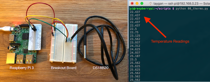
In this post, I'll show how you can build a temperature monitor using a Raspberry Pi and the DS18B20 one-wire digital sensor. The project build time is about 5 - 10 minutes. We will start off by putting together the actual circuit, enable the modules via SSH and finally get our temperature readings with some Python code. When you're all said and done, you should end up with something similar to that below.
1. Requirements
- 1 x Raspberry Pi (Note: The model I am using specifically is the Raspberry Pi 3 Model B v1.2)
- 1 x Breakout Board
- 1 x DS18B20 One-Wire Digital Temperature Sensor
- 1 x 4.7k Ω resistor
- 3 x Female-to-Male Jumper Wires
- 2 x Male-to-Male Jumper Wires
2. The Circuit
- Connect a Female-to-Male Jumper Wire (red) from the 3.3V to the +ve rail.
- Connect a Female-to-Male Jumper Wire (yellow) from the GND to the -ve rail.
- Connect a Female-to-Male Jumper Wire (green) from GPIO4 to Pin 15F.
- Connect a Male-to-Male Jumper Wire (red) from the +ve rail to Pin 14F.
- Connect a Male-to-Male Jumper Wire (yellow) from the -ve rail to Pin 13F.
- Connect the 4.7k Ω resistor to pins 14H and 15H (i.e. between +ve and data).
- Connect the DS18B20 sensor to the breakout board:
- Yellow (GND) to Pin 13J.
- Red (VCC) to Pin 14J.
- Green (DATA) to Pin 15J.
Note:
- The colours on the output leads of your DS18B20 may vary. For example, another version of the sensor might have Black (GND), Red (VCC) and Green (DATA).
- The colours of the jumper wires is not important. I have simply remained consistent with the colours of the output leads from the DS18B20 to make the circuit diagram easy to follow.
3. Add Support for the DS18B20
Now that our circuit is wired up, plug in your micro USB cable to power up the Raspberry Pi so we can execute the following commands via SSH.
1. Open the boot config file.
sudo nano /boot/config.txt2. Navigate to the bottom of the file and enter the following. Once done, to save and exit press: Ctrl+X, Y, Enter.
dtoverlay=w1-gpio3. Reboot.
sudo reboot4. Test the Temperature Sensor
Once the Raspberry Pi is back online, SSH back in and execute the following commands.
1. Enable the probe.
sudo modprobe w1-gpio
sudo modprobe w1-therm
2. Change directories.
cd /sys/bus/w1/devices3. Type ls to list the contents of the directory. You should find a folder similar to mine (28-011620f167ee), this is your device ID.
4. Change into this directory. Note: Your device ID will differ.
cd 28-011620f167ee5. Run the following command.
cat w1_slaveIf successful you should see output similar to what I have below. The second line contains our temperature t=22937 (i.e. 22.937° Celsius).
5. Programmatic Access via Python
Below is some sample code you can copy and paste to programatically get temperature readings and output to console. Note: You will need to update the code for your unique device ID.
import os
import time

os.system('modprobe w1-gpio')
os.system('modprobe w1-therm')

base_dir = '/sys/bus/w1/devices/'
device_id = 'YOUR_DEVICE_ID'
device_file = base_dir + device_id + '/w1_slave'

def read_temp_raw():
    f = open(device_file, 'r')
    lines = f.readlines()
    f.close()
    return lines

def read_temp():
    lines = read_temp_raw()
    while lines[0].strip()[-3:] != 'YES':
        time.sleep(0.2)
        lines = read_temp_raw()
    equals_pos = lines[1].find('t=')
    if equals_pos != -1:
        temp_string = lines[1][equals_pos+2:]
        temp_c = float(temp_string) / 1000.0
        return temp_c

while True:
        print read_temp()
        time.sleep(1)
6. Video
That's it! In a future post I will be looking to bring all this together to explore some of IoT capabilities within Azure, so stay tuned...


